What Is a Bearing Lock and How Does It Work?
A Bearing Lock secures a bearing to a shaft and helps prevent unwanted movement during operation. The term covers several designs, not one universal part. Some bearings use a locknut and washer. Others rely on an eccentric collar or set screws. Each method applies force differently, so the correct choice depends on the shaft, bearing, load, and operating conditions.
A representative maintenance-engineer perspective, expressed here by fictional specialist Alex Morgan, is: “A bearing lock works only when its fit, tightening method, and alignment match the application.” This is an illustrative quotation, not a verified statement from a real industry expert. In practice, installation details matter. A locknut tightened unevenly can affect bearing alignment. A collar that is too loose may allow the bearing to creep along a polished shaft. Small errors can leave marks, create vibration, or shorten service life. Not dramatic. Still costly.
This guide explains what a Bearing Lock does, how common locking styles work, and where each design fits. It also looks at installation checks, typical failure signs, and safe removal. Always follow the bearing and locking-device manufacturer’s specifications; recommended torque and procedures vary. The terminology itself can be confusing, and a locking device does not correct a poor shaft fit. That distinction is easy to overlook.
What a Bearing Lock Is and What It Does
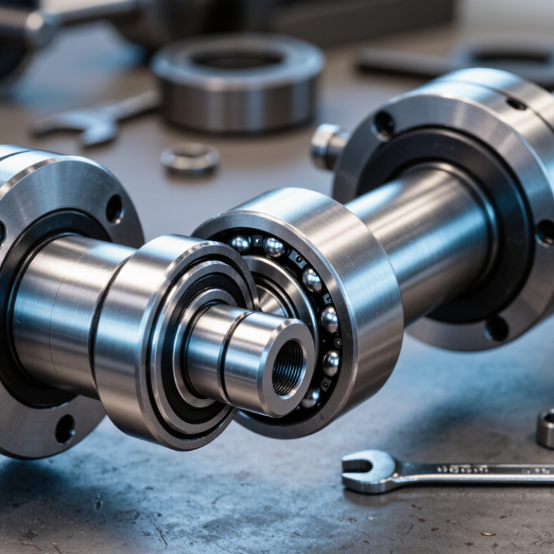
A bearing lock is a fastening feature that holds a bearing’s inner ring in position on a shaft. It helps prevent unwanted slipping or rotation between the ring and shaft while the bearing supports a moving load. Common designs use a set-screw collar, a tapered adapter sleeve, or a locknut. The right type depends on the bearing, shaft, load, and operating conditions. It is a small part, but a loose lock can cause vibration, wear, and poor alignment.
During installation, the lock applies pressure that secures the bearing without replacing the bearing’s rolling elements. A set screw presses against the shaft; a tapered sleeve tightens around it as a nut is turned. The connection must be secure, not forced. Excessive tightening can damage the shaft or affect bearing clearance. In practice, alignment can be less than perfect, so check the assembly after tightening rather than assuming it is sound.
Tips: Clean the shaft and locking surfaces before fitting. Use the specified tightening method, and check for movement after a short run. Watch for heat, noise, or vibration. Small changes matter. If the lock loosens repeatedly, inspect the shaft surface and confirm that the lock type suits the application.
Key Components of a Bearing Lock
Key Components of a Bearing Lock
A bearing lock secures a bearing’s inner ring to a rotating shaft, helping limit slipping during operation. Its parts vary by bearing design. A conveyor roller may use a compact collar, while a larger shaft can use a sleeve and locknut. Small parts matter.
A set-screw collar uses one or more screws that press against the shaft.
An eccentric locking collar has an offset bore; turning the collar engages it with the bearing ring.
Adapter-sleeve assemblies use a tapered sleeve, locknut, and often a tabbed washer. The taper creates a tight fit as the nut advances.
Each method transfers load differently, so parts should not be treated as interchangeable.
The shaft and bearing inner ring are also essential to the locking arrangement. Clean contact surfaces help prevent false seating, and the correct tightening procedure depends on the design. During inspection, look for a loose screw, shifted collar, or washer tab that is not engaged. These details can be easy to miss. One limitation is that a lock may appear secure while still being misaligned; careful fit checks matter more than appearance alone. Use the specified tightening guidance, since excess force can damage threads or bearing components.
How a Bearing Lock Secures a Bearing to a Shaft
A bearing lock secures the inner ring to a shaft, helping prevent unwanted movement during operation. Common designs use set screws, an eccentric collar, or an adapter sleeve. Each creates a mechanical grip, but the installation steps differ. With a set-screw design, the installer positions the bearing and tightens the screws against the shaft. An eccentric collar turns against the inner ring before its screw is tightened. Adapter sleeves use a tapered fit, drawing the bearing onto the shaft as the nut advances. No magic is involved. Clean surfaces and correct alignment matter: dirt, burrs, or uneven tightening can shift the bearing or damage its fit.
A practical check is to confirm the shaft size, bearing arrangement, and specified tightening method before assembly. Do not assume that tighter is always safer; excessive force can distort components. ISO 281:2007 defines basic bearing rating life at 90% reliability under stated operating conditions. That figure is not a guarantee for a particular installation. A loose or misaligned lock can alter the bearing’s operating conditions and shorten service life. After fitting, check that the bearing turns smoothly and that the shaft and inner ring show no visible movement. It is not foolproof. Recheck the assembly after initial operation when the application allows; vibration or heat may reveal a problem that a bench inspection missed.
Common Bearing Lock Designs and Their Differences
A bearing lock holds a bearing firmly on its shaft and helps prevent unwanted movement during operation. The locking design affects installation, adjustment, and maintenance. Set-screw locking uses one or more screws pressed against the shaft. It is compact and straightforward, but the screw tips can mark the shaft. This may complicate later removal. Eccentric-collar locking uses a collar that turns slightly against the bearing’s inner ring. That twist creates a grip. It works well in many moderate-duty applications, though correct rotation and tightening matter.
Adapter-sleeve designs use a tapered sleeve between the bearing bore and shaft. Tightening a nut drives the sleeve into the bearing, creating a close fit. This approach suits larger shafts and can allow adjustment, but installation needs care: excessive tightening may reduce internal bearing clearance. Split-clamp locks grip the shaft through a slotted collar tightened by bolts. They spread the clamping force more evenly and usually avoid screw-point damage. A useful detail: check the shaft surface and available maintenance space before choosing. A lock that looks simple on a drawing can be awkward beside a guard or frame. There is no universally best design; load, vibration, shaft condition, and removal needs all influence the choice.
What Is a Bearing Lock and How Does It Work? - Common Bearing Lock Designs and Their Differences
| Lock design |
How it works |
Typical shaft fit |
Advantages |
Considerations and common uses |
| Set-screw lock |
One or more radial screws press against the shaft to hold the bearing inner ring in position. |
Usually a straight cylindrical shaft; a flat or shallow locating dimple may be used where specified. |
Simple to install and remove; does not require a tapered shaft or separate adapter sleeve. |
Screw tips can mark the shaft, and holding performance depends on correct tightening. Common in mounted bearing units and moderate-duty applications. |
| Eccentric locking collar |
A collar with an offset bore engages a matching eccentric shoulder on the bearing inner ring. Turning the collar wedges the two parts together; a set screw typically helps secure the collar. |
Straight cylindrical shaft. |
Quick, straightforward installation and no separate locknut or adapter sleeve. |
The collar must be turned in the correct direction and secured according to the bearing instructions. Often used on conveyor and agricultural equipment; verify suitability for reversing rotation. |
| Tapered adapter sleeve with locknut |
A locknut drives a tapered-bore bearing onto the adapter sleeve’s taper. The sleeve grips the shaft, while the nut and locking device retain the assembly. |
Typically a cylindrical shaft; the sleeve provides the tapered mounting interface. |
Provides a firm fit without relying on screw tips against the shaft; can simplify mounting and removal of tapered-bore bearings. |
Mounting depth affects bearing internal clearance, so installation must follow the specified procedure. Common in larger or higher-load shaft arrangements. |
| Concentric clamp lock |
A split or clamping inner ring is tightened around the shaft, applying circumferential clamping force rather than relying on a single screw point. |
Straight cylindrical shaft with an appropriate fit and surface finish. |
Evenly distributed grip can reduce localized shaft marking and is generally suitable for reversing rotation when properly installed. |
Requires access to the clamping fasteners and correct tightening. Used in some mounted bearing units where concentric clamping is preferred. |
Selection depends on shaft size and condition, load, rotation direction, vibration, installation access, and the bearing manufacturer’s mounting instructions.
Installation, Inspection, and Maintenance Considerations
A bearing lock secures a bearing’s inner ring to a shaft, helping prevent unwanted movement under load. Depending on the design, it may use a set screw, eccentric collar, or tapered sleeve. Correct fit matters. Clean the shaft and bearing bore before assembly; grit can prevent proper seating and damage contact surfaces. Follow the specified tightening sequence and torque, using a calibrated tool rather than guessing by feel.
During installation, align the bearing with the shaft and avoid striking the ring directly. Tighten evenly, then check that the shaft turns smoothly without binding. A lock that feels tight may still be seated incorrectly. After operation begins, inspect for looseness, fretting marks, unusual heat, and vibration. Record observations so changes are easier to detect. Inspection intervals should reflect speed, load, contamination, and duty cycle—not just a calendar reminder.
Tips: Isolate equipment before inspection. Wipe away grease carefully and look for polished movement marks around the shaft. Recheck fasteners only as the design allows; repeated tightening can deform parts or damage threads. Replace worn locking components instead of applying extra force. A misaligned shaft can resemble a loose lock, so verify alignment before blaming the hardware.
Bearing Locknut: Theoretical Axial Advance
For a metric M20×1.5 thread, one full nut revolution advances the nut 1.5 mm along the thread. The values below show the theoretical advance at quarter-turn intervals.
This is thread geometry, not a tightening or preload specification. During installation and inspection, follow the bearing and locknut manufacturer’s instructions; check the locking feature is engaged and inspect for loosening or damage during maintenance.